Quantcast
Channel: Tiny Devices
Viewing all 72 articles
Browse latest View live

i.MX6SX - UDOO NEO Early hardware prototype

$
0
0
A few weeks back I received an early hardware prototype of the UDOO NEO. It hosts one of the newer members of the i.mx6 family, the i.MX 6SoloX which integrates a Cortex A9 with a Cortex M4. This seems to be Freescales first venture with a heterogeneous SOC, interestingly there may more down the road with the introduction of the i.mx7 (Cortex A7 + Cortex M0/M4).

What is striking about the i.mx6sx architecture is that the primary processor is the Cortex A9. Therefore to boot the i.mx6sx requires uboot or (another i.mx6 bootloader) to be present. Once the A9 is active the secondary processor (Cortex M4) can be brought on-line, either through uboot or after the A9 starts running Linux. In either case, application code (and/or bootloader) has to be made available to the M4 via on board flash or loaded into RAM. The M4 is brought on-line via a Reset following the standard Cortex M4 start up process of booting from a vector table at address zero (which in the A9 world is mapped to 0x007f8000). From what I understand address zero seems to be 32K of TCM (Tightly-coupled memory). The M4 seems to be capable of interacting with most of the on-board peripherals provided by the i.mx6sx. Other areas of interests on the i.mx6sx are :
  •  An semaphore mechanism (SMEA4) to aid processor contention 
  • A messaging mechanism (MU) to enable the two processors to communicate and coordinate by passing messages
The i.mx6sx isn't intended as multimedia processor and this is highlighted by the lack of a VPU and the inclusion of a low spec GPU, the Vivante GC400T which claims up to 720p@60 fps and is limited to Open GL ES 2.0.

What is unusual is the inclusion of the video analogue to digital converter (PAL/NTSC). Given that Freescale target market is Automotive I suspect this is for applications like reverse parking.

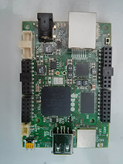
In it's current form the NEO has a small footprint  (850mm x 600mm)  and the notable on board peripherals are:
  • Ethernet (10/100) - KSZ8091RNA
  • Wifi/bluetooth - WL1831MOD
  • HDMI  - TDA19988
  • Gyroscope - FXAS21002C
  • Accelerometer + Magnetometer - FXOS8700CQ
  • 2 User defined LED's
  • 1 USB 2.0 type A female connector
The FXAS21002C and FXOS8700CQ are currently interfaced through i2c and the datasheets indicate a maximum clock speed of 400Khz (in Fast Mode).


Software for the NEO is still in early stages of development, so it's taken me a couple of weeks of development effort to get uboot and a kernel functioning. Above is a short video demonstrating the fruits of my efforts. On power up we launch a small application on the M4 from uboot which toggles (flashes) the Red LED and continually outputs a message on Uart 2 (shown later in the video). We then boot the kernel to a Ubuntu rootfs and launch an Open GL ES application on which outputs a rotating square to hdmi (720p).  The speed of rotation increases the more the board is tilted to the left or right (using the accelerometer). Note the Red LED continually toggles highlighting the fact that the cortex M4 is uninterrupted by the A9.

Having started to develop code for the TDA19988 interface, one useful feature of this controller is the ability to support DVI or HDMI displays. The downside being that the GPU struggles past 720p in my tests.

Another point to note is that there is no on board flash for the M4. Therefore code for the M4 has to be loaded into RAM which means reserving a small portion away from kernel. This introduces another layer of complexity as the reserved area needs to be protected from accidental access.

Developing for the board definitely gives you a good insight in its usability. This leads to my wish list, if the board were to be improved :

1. 2 x USB 2.0 type A connectors, for keyboard & mouse useful when used with HDMI.
2. 2 x Ethernet (definitely make it stand out from the competing SBCs).
3. Use SPI for FXAS21002C & FXOS8700CQ or ideally replace with 9 axis IMU.
4. I'd prefer the sensors to be on a separate pcb that can be connected via a jump cable to the main board. The main reason being that manoeuvring the board to test the sensors with the cables attached (ethernet, serial, power, usb, hdmi) isn't that practical.
5. On board JTAG support, it is very difficult to debug the M4 code without it!
6. There are two uart outputs, one for A9 serial console and other for the M4 on the NEO. Similar to the UDOO it would be very useful if these were exposed via single usb connector. In the current design you need to hook up 2 serial-to-usb adapters.

i.MX6SX - Video processing via VADC & PXP (UDOO Neo)

$
0
0
Unlike the rest of the i.mx6 family, the i.mx6sx has limited hardware video decoding support for example there is no h.264 or mpeg support. The i.mx6sx hosts a simpler video analogue to digital converter (VADC) which allows the conversion of a NTSC or PAL signal to a YUV444 format. The YUV444 is slightly unusual in that its encoded as a 32 bit value which equates to YUV32 in V4L2 terms. Given the unusual YUV32 output decoding becomes more interesting because it heavily relies on the PXP (Pixel Pipeline) engine for colour space conversion and onward rendering to a display. The PXP can be considered a smaller brother of the IPU (Image Processing Unit) as found on the rest of i.mx6 family. In addition to colour space conversion the PXP has the capability to flip (horizontal/vertically), scale and blend/overlay images from multiple sources. The one caveat is that PXP on the i.mx6sx has limited input and output formats that it can accept.


Engine check sensor image
To give you an idea of the what the PXP can do, the video above shows the output of a NTSC camera blended with a graphics overlay. The camera is actually a parking (reversing) camera (courtesy of the UDOO team), this is highlighted by the red/yellow/green lines and the blinking 'STOP' text which form part of the camera output. Given the automotive theme the graphics overlay represents a engine check sensor dash. The output video (720x480) fits nicely on the UDOO 7" LVDS display. As the UDOO Neo is targeted towards sensor technology (IOT),  we use the tilt angle from the gyroscope to determine the amount of alpha blending to apply (the graphics fade away or become fully visible).  Furthermore depending on axis of the tilt the combined video output is flipped horizontally or vertically (in real time) noticeable by the 'STOP' text and graphics appearing reversed or upside down.

Given the above, I have put together a simple example that demonstrates to how read the camera output and pass it to the PXP for onward processing. The example is partially based on existing freescale code snippets but modified to use the PXP and then simply renders to a frame buffer. The example will only run against a frame buffer and not on X11. Unlike the above video, the example does not use GPU hardware acceleration therefore the CPU usage will be high. In order to build the example you require PXP header/library to be built and installed which are part of the imx-lib package.

To build:

make clean
make

To run:

./imx6sx_vdac_pxp

Optional parameters

-t Time in seconds to run
-h flip image horizontally
-v flip image vertically
-i invert colours


i.MX6SX - Realtime CAN interfacing Part 1 (UDOO Neo)

$
0
0
One of the most promising capabilities of the i.mx6sx is combing the Cortex M4 with the on board CAN interfaces. This feature opens up a number of possibilities for deploying the i.mx6sx for a varied range of automotive solutions where real-time processing of CAN messages is handled by the M4 and the A9 kept for non-critical processing. To demonstrate this, lets take a simple use case of driving an automotive instrument cluster.  In a series of blog posts I will cover how we can drive the instrument cluster initially from the M4, then from the A9 communicating via MU (Messaging Unit) to M4 and finally by a on screen virtual dials mimicking the actual instrument cluster dials.


For this exercise we used an instrument cluster pulled from a Mazda RX8. The RX8 instrument cluster interface is partially analogue and partially digital. The digital interface is provided through a high speed CAN (500 Kbps) interface that drives the dials (RPM, Oil, Temperature) , digital speedometer and a number of warning indicators. Time pending I may cover the RX8 instrument cluster CAN interface in more detail in another blog. The target board for development was the UDOO NEO complemented with SN65HVD230 CAN Transceivers.

For this first demonstration a FreeRTOS application was developed to run on the M4 that regularly sends CAN messages to the cluster and dumped CAN messages generated on the bus from the cluster to the serial port. In order to drive the dials and suppress the warning indicators, the instrument cluster requires a regular feed of CAN messages sent at 10 milliseconds intervals. When the cluster is active it also generates CAN messages roughly at 50 millisecond intervals.

The video above shows the application (rx8_can) being launched from Uboot, before launching the application notice that all warning indicators lights are active on the instrument cluster. After the application is launched all warning indicators are cleared and the RPM gauge and speedometer are active. The application also dumps the instrument cluster generated CAN messages to the serial port (shown in the terminal to the right). After launching the application we boot to a Linux console to demonstrate the A9 is unaffected while the M4 continues to control the instrument cluster.

In the next post I aim to demonstrate how we can utilise the Message Unit to allow the A9 to control the instrument cluster by communicating with the M4.

i.MX6SX - Realtime CAN interfacing Part 2 (UDOO Neo)

$
0
0
As mentioned in my previous post the next stage of development with the RX8 instrument cluster is to offer the ability to control the gauges/indicators on the cluster from the A9 side. In the last post I also pointed out that to keep the cluster active the M4 side has the responsibility of regularly sending/receiving CAN messages from/to the cluster. Hence we can't use the CAN interface from the A9, instead we get the A9 'to talk to' the M4. Within the i.mx6sx the Messaging Unit module enables the two processors to communicate with each other by coordinated passing message. We can make use of this feature to send messages to the M4 from A9 to ask it to update the cluster and use the M4 to forward CAN messages received from the cluster to the A9. By the way, this all happens while the M4 also is feeding the cluster with its own CAN messages. For the i.mx6sx the inter-processor communication is abstracted and implemented through the Remote Procedure Messaging (RPMSG) framework which is supported both in the Linux and FreeRTOS BSP.


Compared to the last demonstration, the main change to the configuration is the introduction of a relay board so that the instrument can be powered on and off (the Power Control box in the diagram) by the M4.


The M4 firmware has been amended to accept commands from the A9 via RPMSG. On the A9 side we have 2 applications:

1. read_can - Which constantly reads CAN messages sent from the instrument cluster via the M4 .
2. cluster_control - Controls the instrument cluster via the M4.

cluster_control has the following capabilities through a number of command line options:

-i  - turns the instrument on/off
-r  - set the RPM
-s  - set the SPEED (in kilometres although display is in mph)
-b  - set Battery Warning indicator
-o  - set Oil Warning indicator
-c  - set Cruise control indicator


The short video demonstrates two applications running on the A9, read_can is running in the window on the left and on the right cluster_control is used to manipulate the cluster. Note that prior the 2 applications being launched, the M4 was preloaded with new firmware and RPMSG initialised on the A9 side. Once cluster_control changes the cluster state, the M4 is responsible for continuing updating the instrument cluster with the new state until the next change. 

Now that we have the ability to control the cluster and receive messages from the A9 side, in the final post I will demonstrate how another feature of i.mx6sx can be used with it.

i.MX6SX - Realtime CAN interfacing Part 3 (UDOO Neo)

$
0
0


In the last post we covered how the RX8 instrument cluster could be controlled from the A9 side. Given the A9 side is feature rich in its capabilities if offers numerous possibilities. As a simple demonstration we will attempt to replicate the RPM and Speed gauges and two warning indicators on the hdmi (720p) display to represent a simplified virtual instrument cluster. The main challenges here are:

1. On screen widget need high performance.
2. Keeping the on screen gauges/warning indicators in sync with the instrument cluster.
3. Minimising CPU usage.


In the video, the on screen RPM gauge (on left fairly) accurately tracks the RPM needle on the instrument cluster. The on screen Speed gauge (on the right tracks) the digital Speed indicator. We also toggle the battery and oil warning indicators on the screen and cluster. Notice that the cluster_gauges application is consuming rough 10% of the CPU.

In order to deliver the necessary performance the on screen gauges were rendered using custom Open GL ES 2.0 code. Note the graphic images used for gauges are modified versions derived from this Android Ardunio project. Compared to the previous post there is now a single application (cluster_gauges) on the A9 side which renders the widgets but also controls the instrument cluster through the M4.


I hope through these 3 blog posts have I managed to demonstrate how the M4 and A9 processor can be combined to provide a rich real-time interface and data distribution mechanism for your applications.


i.MX6SX - Prototype VW (VAG) vehicle diagnostic adapter for KWP2000 services (UDOO NEO)

$
0
0

An interesting use case for the i.mx6sx is as vehicle diagnostic (or interface) adapter. In this blog I will demonstrate how we can re-purpose a UDOO NEO as a prototype diagnostic adapter.


The adapter targets VW vehicles supporting KWP2000 services. Typically an adapter requires a real time interface to the vehicle in order to keep the diagnostic session alive after establishing communications with an ECU.  The real time needs can easily be met on the M4 and we can exploit the A9 side to offer data transformation and API services, for example to make the data available a Mobile application. The end goal is demonstrated in the video where a custom developed Android Application retrieves diagnostic information from the vehicle in real time. The application communicates over Wifi with the NEO which in turn is connected to the vehicles ODB-II port.

The application is first used to query the vehicle for a list of available ECUs (modern vehicles can contain tens of ECUs). For each ECU the physical address and overall status is displayed (OK or has DTC errors).

Subsequently after selecting an individual ECU the application retrieves information about the ECU including the short/long coding value (if applicable).


Although the video demonstrate a few KWP2000 services being invoked, its actually possible to invoke most if not all of the services available. Furthermore it could be enhanced to support UDS services.


At a hardware level VW KWP2000 is supported through CAN (some older vehicles use K-Line) and is accessible through the vehicles on board 16-pin OBD-II connector. For the prototype (in the photo to right) the NEO is simply connected to a SN65HVD230 which in turn is connected to the CAN pins of the OBD-II connector.


Typically VW KWP2000 services are supported over VW's proprietary TP2.0 protocol. TP2.0 is used to establish a session and pass datagrams between 2 ECUs, one of which is our case is the NEO and normally referred to as the 'tester'. Implementing TP2.0 is a challenge as accurate timings are required to correctly deal with time out and error scenarios in addition to implementing logic to cater for varying ECU behaviours depending on their age.  Above TP2.0 is the KWP2000 protocol which implements a simpler request response model. As shown the diagram below a complete TP2.0 and KWP2000 stack was developed to run on the M4.


On the A9 side KWP2000 services are exposed through a custom API interface that when invoked communicate with the M4 over a bidirectional link. The A9 allows the data to be enriched and transformed eg XML/JSON before being exposed via a number of network interfaces such as bluetooth, wifi or even ethernet. For the demo its done by enabling a  Wifi Access Point on the NEO. For those shaped readers you will notice the prototype uses a NEO Basic which has no on board wifi support, instead a wifi dongle was plugged into the USB port to create the Access Point.

Adding a DS3231 Real Time Clock to UDOO NEO/QUAD

$
0
0
Its well know that the in-built RTC on the imx6 processor isn't the best in terms of battery life (performance).  Using an external RTC provides better battery life and fortunately the process isn't too complicated implement. The DS3231 is a popular RTC especially with the RPI community given ease of integration (via I2C) and accuracy. There's a few variations of the DS3231 for the RPI and the one I using is the one below which can be easily sourced.


In the image I have highlighted the pin out to simplify wiring. I'm going to take the UDOO NEO as a example and use I2C4 (alternatively you can use I2C2). For I2C4 wire SDA to pin 35 and SCL to pin 34 on header J5, 3.3v and GND are available on J7. On power up you can verify the DS3231 is visible by executing:

udooneo:~# i2cdetect 3

which should return the DS3231 at address 0x68.

WARNING! This program can confuse your I2C bus, cause data loss and worse!
I will probe file /dev/i2c-3.
I will probe address range 0x03-0x77.
Continue? [Y/n] Y
     0  1  2  3  4  5  6  7  8  9  a  b  c  d  e  f
00:          -- -- -- -- -- -- -- -- -- -- -- -- --
10: -- -- -- -- -- -- -- -- -- -- -- -- -- -- UU --
20: UU -- -- -- -- -- -- -- -- -- -- -- -- -- -- --
30: -- -- -- -- -- -- -- -- -- -- -- -- -- -- -- --
40: -- -- -- -- -- -- -- -- -- -- -- -- -- -- -- --
50: -- -- -- -- -- -- -- -- -- -- -- -- -- -- -- --
60: -- -- -- -- -- -- -- -- UU -- -- -- -- -- -- --
70: -- -- -- -- -- -- -- --

                        
Next step is to enable kernel support by enabling the Dallas/Maxim DS1307 driver as below.


Build the kernel and modules (this is important). Lastly we need add the DS3231 to the device tree to I2C4, below is an example,

diff --git a/arch/arm/boot/dts/imx6sx-udoo-neo.dtsi b/arch/arm/boot/dts/imx6sx-udoo-neo.dtsi
index abbf0d8..2ffa6cb 100644
--- a/arch/arm/boot/dts/imx6sx-udoo-neo.dtsi
+++ b/arch/arm/boot/dts/imx6sx-udoo-neo.dtsi
@@ -298,6 +298,11 @@
                compatible = "fsl,fxas2100x";
                reg = <0x20>;
        };
+
+       rtc@68 {
+               compatible = "dallas,ds1307";
+               reg = <0x68>;
+       };
 };


Rebuild the relevant dtb file depending on your set-up. Deploy the newly generated kernel, modules and dtb to the NEO.

On power up the kernel output should include the following lines ( try dmesg | grep ds1307)

[    8.095963] rtc-ds1307 3-0068: rtc core: registered ds1307 as rtc0
[    8.095989] rtc-ds1307 3-0068: 56 bytes nvram


If all is ok we can query the clock for it current time by using the hwclock utility:

udooneo:~# hwclock -r
Tue 24 Jan 2017 12:32:25 PM UTC  -0.858087 seconds


We can sync with the ntp time:

udooneo:~# hwclock -s

On reboots the RTC time may become corrupt with the udooubuntu release to overcome this the ntp needs to be disabled with the following commands:

echo manual | sudo tee /etc/init/ntp.override
timedatectl set-ntp false

The timedatectl command is extremely useful as it provides a complete picture of the system and rtc times. For example to sync RTC with system time:

udooneo:~# timedatectl
      Local time: Fri 2016-01-01 01:18:06 UTC
  Universal time: Fri 2016-01-01 01:18:06 UTC
        RTC time: Tue 2017-01-24 12:40:36
        Timezone: Etc/UTC (UTC, +0000)
     NTP enabled: no
NTP synchronized: no
 RTC in local TZ: no
      DST active: n/a
udooneo:~# hwclock -s
udooneo:~# timedatectl
      Local time: Tue 2017-01-24 12:42:03 UTC
  Universal time: Tue 2017-01-24 12:42:03 UTC
        RTC time: Tue 2017-01-24 12:42:03
        Timezone: Etc/UTC (UTC, +0000)
     NTP enabled: no
NTP synchronized: no
 RTC in local TZ: no
      DST active: n/a


i.MX6SX - Pulse oximetry with MAX30100, SSD1306 and UDOO NEO

$
0
0
In this blog I demonstrate how the cortex m4 on the imx6sx could be used to develop a Pulse Oximeter.


I chose the max30100 because its features an integrated pulse oximetry and heart-rate monitor sensor. Unfortunately Maximi provide little documentation or application notes covering how best to determine heart rate or spo2 values using the data returned from the sensor. The sensor hosts an IR and RED LED that can be adjusted to provide pulses for spo2 and heart rate measurements. As a trade off between adequate data samples, i2c bus speed and post measurement hr/spo2 calculation processing the max30100 was configured to return 100 IR and RED values per second. Below is a graph showing raw data values gathered from the NEO at a 100 readings per second.


For spo2 calculation we have taken a simplified approach of taking the AC components of both signals and determining the ratio. The ratio is referenced in an memory table containing empirical sp02 values. Hence the spo2 isn't clinically accurate, for greater accuracy the table would normally be based on experimental measurements from healthy patients cross referenced against clinically accurate readings.

As shown in the graph the IR values are smoother than RED values possible due to secondary emissions from the RED LED. For this reason the IR value are normally used to determine the heart rate. The heart rate is calculated by feeding the IR values in to a first order 6Hz low pass filter which in turn are used to calculate the time interval between 2 peaks. Sample output of applying the low pass filter is shown below ignore the graph labels, top is IR values, bottom is low pass filter.


I also hooked up a  SSD1306 oled display to the same i2c bus so that the calculated heart rate and spo2 values are displayed. The main challenge of this exercise has been to be ensure the code running on the M4 is as efficient as possible because there are many time critical elements such reading data samples, hr/spo2 calculation and display updates which can interfere with the output results. As with my previous examples on the imx6sx this was developed using the FreeRTOS sdk.


i.MX6SX - Using the cortex M4 on a UDOO NEO to drive a $4 Touch Screen

$
0
0
The challenge here was to see if a ultra cheap touch screen could be made to work with the cortex M4 on the UDOO NEO. The video (below) demonstrates its possible, the M4 is controlling the display and a simple UI allows the toggling of the green LED.


I managed to pick up a 2.0" touch screen for around $4, although the screen is on the slightly small side, it still manages to support a resolution of 320x240. Normally these type of screens are sold into a secondary market with the hope that they can be interfaced to an Arduino, their primary use seems to a PDA or home communication device given the imprinted icons (which aren't removable).


The display supports a 8 bit parallel LCD interface (using the S6D1125) along with a 4 wire resistive touch. The downside with using such a display is that it requires a large number of pins, in our case 12 GPIO pins and 2 analogue pins (for resistive touch).

The code to drive the display was built using the i.mx6sx FreeRTOS sdk.

i.mx6sx - One Wire Digital Temperature gauge using DS18B20 + UDOO Neo + LCD

$
0
0


The challenge here was to implement the Dallas one wire protocol so that two DS18B20 sensors could be wired to the cortex M4 to form the basis for a temperature gauge. I recycled the LCD display from the previous post to display temperature readings using 'ring meter' widgets. The end result is that the M4 is used for reading DS18D20 sensors and updating the 'ring meter' widgets. In the video we have one sensor in a 3 pin TO-92 package reading room temperature and the other as a waterproof probe dipped into hot/cold water.

The DS18D20 one wire protocol simply requires a gpio pin that can be toggled between input and output modes albeit using precise timings to the microsecond (between 1 and 480 microseconds). The protocol and timings are described in the DS18B20 datasheet. To achieve the necessary level of time precision we utilised the imx6 Enhanced Periodic Interrupt Timer (EPIT) timers sourced from a 24Mhz clock. Since there are two DS18B20 sensors on the one wire bus we first query for the address of the sensors and then in turn poll for the temperature from each which takes approximately 480 microseconds.

i.mx6sx - SPI interfacing an OLED display for fast updates using the cortex M4 on the UDOO Neo

$
0
0


It has taken me a considerable amount of time to prove that the SPI interface can be made to work with cortex M4 on the UDOO Neo. To demonstrate the speed of SPI I chose to interface with a SSD1306 OLED which can be driven at a clock speed of 8Mhz. Which theoretically should allow a complete RAM buffer to transmitted to the SSD1306 in a very short time period hence offering fast screen updates. To control the speed of screen updates I hooked up an old potentiometer to the ADC input. By varying the potentiometer we control the rate of updates from slow to fast as shown in the video.

The SPI interface is configured for Master mode using interrupts for data transmission resulting in acceptable performance. To reduce interrupt latency further, DMA could be used to transmit the whole RAM buffer in one go.
 
I chose to use ECSPI 2 (normally allocated to the A9 side) and not ECSPI 5 because after reviewing the schematics I think there is a hardware bug with ECSPI 5 as the ECSPI5_SCLK line is shared with Red on board LED (see SPI3_CLK on J6 connector).

This is a C application developed using i.mx6sx FreeRTOS SDK. The graphics rendering code was converted from the Haricord example by hwiguna.

i.mx6sx - Tiny NEO Scope

$
0
0


This project span from two requirements, firstly testing the performance of the ADC (analogue to digital) and ECSPI interfaces when running against the M4. Secondly as a diagnostic aid to verify low bandwidth clock signs (<100Khz) from the PWM or clock/GPIO pins were correctly mux'd from the A9 side. The end result is a simple low bandwidth (<100Khz) oscilloscope. In the above video we first demonstrate the capture of the 50Khz PWM (50% duty cycle) which is generated from the A9 side, see how scope manages to display the signal and correctly calculate the frequency. Secondly we feed the scope a PWM ranging from 3Khz to 95Khz to demonstrate its ability to track and best calculate the input frequency of the signal.

The imx6sx ADC is rated to produce up to 1 Million samples per seconds, however the Reference Manual isn't particularly clear on settings to get this level of performance. It's clear that the fastest conversion are only possible in 8 bit mode (lowest precision) using the IPG clock. From our testing we roughly achieved 500 thousand samples per second by applying no hardware averaging and no clock divider ratio. By disabling hardware averaging we trade off precision for speed in 8 bit mode.

The scope simply consist of reading an ADC pin (in our case A3), buffering 128 samples, outputting samples to the OLED display through the ECSPI interface clocked at 8Mhz. A primitive trigger mechanism is implemented to catch start of a rising signal. This is complemented with high precision EPIT timer to calculate the frequency of input signal for display.
 

i.mx6sx - M4 SD Card access on the UDOO NEO

$
0
0
In this post I demonstrate that it is possible to interface the M4 to a SD card shield (similar to using an Arduino SD card shield) in order to retrieve or save data locally (without relying on the A9). This work is the result of a larger data logger project, where the A9 remains in sleep mode to conserve power while the M4 performs data logging from numerous sensors.


In the video an SD card shield is interfaced to the UDOO NEO and accessed from the M4. The code initialises the SD card, mounts and reads the FAT32 partition. Subsequently we read bitmap files from the FAT32 partition and display the contents to the LCD display (320x240). Code is written using the FreeRTOS bsp and exeutes on the M4 while the A9 boots linux. Each bitmap file is 230400 bytes and when reading 720 byte blocks  throughput is around 230KB/sec. If we increase the block size to 23040 bytes then throughput is around 340KB/sec.

NEO Connectivty

I chose to use a WeMos data logger shield over a Arduino SD card shield mainly for the following reasons:

1. 3.3v compatible
2. An RTC (plus battery backup) is available on the shield, although the accuracy of the DS1307 compared to DS3231 is questionable.
3. Nice stackable design for inclusion of additional WeMos shields

The shield (just the Arduino equivalent) supports an SPI interface. The Phyical Layer of the SD Card Specification mentions that the primary hardware interface is the SD bus which is implemented through 4 data lines and one command line. On power up the native operating mode of the card is SD bus however it possible to switch the card to SPI bus which is considered a secondary operating mode. The main disadvantages of SPI mode versus SD mode are:

1. The loss of performance single data line versus 4 data lines .
2. Only a subset of the SD commands and functions are supported.
3. The maximum SPI clock speed is limited to 25Mhz regardless of the SD card Class.


Minimum connectivity from a host MCU for SPI mode requires 3 SPI pins plus a GPIO pin for CS.


From the NEO the shield can be connected to ECSPI 2 plus a arbitrary GPIO pin and 3.3v, see above (NEO Connectivity) image for wiring.

Power up and initialisation of the card along with commands and responses are well documented in the Phyical Layer of the SD Card Specification. After powering up the card it should be initialised by applying 74 clock cycles (eg. sending 10 bytes with 0xff as the payload). Followed by CMD0 as the first command to send the card to SPI mode, a positive R1 response will contain 0x01. Next step is to interrogate SD version support by sending CMD8 and lastly we can use ACMD41 to set or determine :

1. Card is initialised
2. Card capacity type (SDHC or SDXC)
3. Switch to 1.8V signal voltage

After initialising the card we can interrogate the card data for example:

1. Read the Card Identification (CID) Register, a 16 byte code that contains information that uniquely identifies the SD card, including the card serial number (PSN), manufacturer ID number (MID) and manufacture date (MDT).

2. Read the Card Specific Data (CSD) Register which defines the data format, error correction type, maximum data access time .. etc


Subsequently I built a simple library to read FAT32 partitions and their file contents as shown in the above screen shot.

In order to improve performance we would need to see if we can enable DMA for the SPI transfers however this represents a challenge as the DMA engine is initialised on the A9 therefore we would need to wait for Linux to boot before accessing the DMA engine.


i.mx6sx - IMU Sensor fusion with the UDOO NEO

$
0
0
A key feature of the UDOO NEO is the hosting of a 9-DOF IMU through the inclusion of the NXP FXOS8700CQ and FXAS21002C sensors. The FXOS8700CQ provides a 6-axis accelerometer and magnetometer and FXAS21002C provides a 3-Axis Digital Angular Rate Gyroscope. Note that these sensors are only available on the Extended and Full models. In the video we demonstrate 9-DOF sensor fusion running on the cortex M4. The M4 fusion output is sent from the serial port and fed to a modified OrientationVisualiser application run on a PC. OrientationVisualiser is Processing application that displays a Arduino like board in 3D is part of the NXPMotionSense library refer to Teensys example and code.


The combination of the two sensors offers the ability to track absolute orientation with respect to a fixed Earth frame of reference with reasonable accuracy. Orientation can be modelled in 3 dimensions and most descriptions refer to the analogy of an aircraft. Where yaw represents movement of the nose of the aircraft from side to side, pitch represents the up or down movement of the nose of the aircraft and finally roll represents the up and down movement of the wing tips of the aircraft. Refer to this post for a detailed description. For our solution the sensor fusion algorithm implements a Kalaman filter. The filter smooths noise from the accelerometer/magnetometer and drift from the gyroscope. We also run magnetic calibration to reduce the effect of hard and soft iron magnetic interference.

Its important to note that the FXOS8700CQ is mounted on the underside of the pcb, however the axes should be aligned to a Cartesian coordinate system that follows the Right Hand Rule (RHR). Therefore its important that X,Y,Z values read from the FXOS8700CQ should to be adjusted accordingly before applying to the fusion algorithm. Although the FXOS8700CQ has been placed at the edge of the board its important to remember that the pcb spacer hole is about a 1 centimetre away. To reduce magnetic interference on the magnetometer a metal pcb spacer or screw shouldn't be used in this hole.

In this example we reallocated I2C4 to the M4 in order read data from both sensors. In our set-up the FXOS8700CQ output data rate (ODR) was 200Hz while the FXAS21002C was configured for 400Hz. As per previous posts the code was developed using the i.mx6sx FreeRTOS SDK.


Machine learning with the i.MX6 SoloX and the Movidius Neural Compute Stick

$
0
0


The i.MX6 SoloX processor is fairly unique in the i.MX6 family primarily because it co-hosts a single Cortex A9 along with a Cortex M4. The heterogeneous architecture proves very useful for hard real-time processing occurring on the M4 while concurrently running a Linux stack running on the A9 (the heterogeneous architecture is implemented on the i.MX8 line of processors). In previous posts using the UDOO Neo I have covered how these features can be exploited when interfacing different peripheral devices. The processor architecture lends itself nicely to IOT (Internet of Things) Edge devices where sensor capture and data preprocessing/conversion can occur on the device before being forwarded to the cloud where a richer set of analytic processing can be performed. If we could perform some (or all) of the analytic processing on the edge device then we might dramatically reduce the amount of device data traffic sent to the cloud. Alternatively the edge device could make decisions for itself and not completely rely on the cloud, furthermore it opens ups the possibility of the edge device partially functioning when the network isn't available. This concept is know as Edge Analytics.

A single Cortex A9 practically isn't up to the job of performing intensive analytical processing especially if we would like to implement a machine learning algorithm. In terms of machine learning techniques Neural Networks are one branch that has gained considerable popularity in the last few years primarily because it offers new avenues for the types of analytical processing that can be done ie image recognition or text processing. The Movidius Neural Compute Stick (NCS) is an intriguing concept as it opens up the possibility of deploying deep neural networks on embedded devices. In the video we demonstrate feeding a number of images (loaded from png files) to a caffe GoogLeNet model, for each inference it displays the top matching label and probability score. As a performance enhancement we utilise the PXP engine to perform hardware image resizing and BGRA conversion before feeding a 224 x 224 image to the model for classification. The resized image is also rendered to the screen (using the 2D acceleration). To gain an acceptable level of performance the application was developed in C/C++.

So, the first challenge was to see if we could get NCS running with the UDOO Neo (the i.MX6SX board). My starting point was referring to the Movidius article of deploying on the Raspberry PI. As mentioned in the article its important to highlight that training, conversion or profiling of the Neural Network can't be done on the embedded device ie "Full SDK mode". This implies that the Neural Network needed to be trained and converted using a standard PC or cloud environment. Deployment to an embedded device is restricted to "API only mode". This first step turned out to be a challenge mainly because my starting pointing was Ubuntu 14.04 and not 16. It took a few days to get the correct packages compiled and installed before caffe would compile without errors. The Neural Compute Application Zoo  provides a number of sample applications, you can use hello_ncs_cpp or hello_ncs_py to verify the OS can communicate with NCS. The other gotach is that the NCS is power hungry and requires a powered usb hub especially if you have other usb peripherals attached. On the NEO the NCS can be plugged directly into the USB type A socket if you don't have a need for additional peripherals.

The second step was to see if we could deploy a Neural Network graph on the NCS and perform simple inferences. Most of the sample applications in the 'Zoo' are Python based with some having further dependency on OpenCV. Unfortunately running OpenCV and Python on Neo would introduce too much of a bottleneck with regards to performance (or in fact most low power ARM embedded devices). The 2 reasons for this are the single A9 core and the fact that the X11 interface doesn't support hardware accelerated graphics. With ARM processors there is trade off between power and performance and for 'always on' IOT devices this does become a major deciding factor. Fortunately caffe provides a C++ interface although there's little documentation available about the API interface. Within 'Zoo' there is  multistick_cpp C++ application which demonstrates communicating with multiple NCS devices.

My starting point was altering multistick_cpp to use one stick with the GoogLeNet model. In multistick_cpp after the GoogleLeNet graph is load subsequent processing can be broken down into two further steps. Firstly it loads, resizes and converts to BGRA a png image file and secondly it sends the image data to NCS for inference and finally displays the result. Sample timings for each steps running on the Neo are shown below.

1. Load png, resize and convert : approximately 800 milliseconds
2. NCS inference : approximately 130 milliseconds

We can't do much about Step 2 without re-tuning (a redesign) the Neural Network or by reducing the image size (possibly leading to less accuracy). Step 1 is slow because the file images are roughly around 800x800 pixels and software resizing to 224 x 224 is painfully slow. Fortunately we can address the resizing and conversion time in Step 1, the i.MX6SX contains an image processing unit known as PXP (Pixel Pipeline) which can rescale and perform colour space conversions on graphic buffers. I re-factored the code in step 1 as below:

1. Use libpng to read the png file
2. Resize and color space the image using PXP
3. 2D blit re-sized image to screen

With the above changes sample timings dramtically improved for step 1 (as show in the video):

1. Load png, resize and convert : approximately 233 milliseconds
2. NCS inference : approximately 112 milliseconds

Hopefully this article provides useful introduction to deploying the NCS with i.MX6 or i.MX7 line of processors. Going forward I would like to get a camera working with Neo and see what FPS rate we can achieve. The other interesting avenue is deploying SSD MobileNet and using the PXP overlay feature to render matches.

I liked to thank motiveorder.com for sponsoring the hardware and development time for this article.

ESP32 - Enabling RS485 half duplex UART support

$
0
0
Although the ESP32 UART claims to support RS485 the documentation provided in the Technical Reference Manual is pretty poor as the register and interrupt descriptions are extremely vague in terms of each feature and its purpose. This is further exacerbated by the fact there are no examples provided in the SDK. The subject has been widely discussed in a espressif forum thread and a pull request was submitted. Unfortunately the main problem with the solution was that spurious break characters were observed in the RX FIFO and needed to be filtered. Another issue is that toggling of RTS pin happens with in the RX interrupt handler, so we can't control at an application level.

Having spent quite a few (or too many) hours debugging the UART behaviour in RS485 mode I think I have an improved implementation for a driver.  Its important to note that the driver only supports half duplex mode, ie only one node on the RS485 bus can transmit at any time. See commits in my fork , the main changes are:

1. The RTS pin is toggled outside of the driver code, ie in the application code therefore data direction and auto direction transceiver are supported.
2. Spurious break characters shouldn't occur in the RX FIFO.
3. Enabling of RS485 interrupts, currently only the collision detection is implemented. Further work is required to correctly handle the framing or parity error interrupts.

The uart_rs485_echo example (under  examples/peripherals/) provides a simple demonstration of its use. The example receives data from the UART and echoes the same data back to the sender. After configuring and enabling the UART we can control the RTS pin using the existing uart_set_rts function to control the data direction pin of the transceiver, note this is optional and can be disabled in the code for auto direction transceivers.

The example has been tested with the following boards :

1. SparkFun Transceiver RS485 Breakout board which hosts a SP3485 transceiver.


2. XY-017 RS485 to TTL Module which is an auto direction transceiver with unmarked ICs.


Machine learning with the i.MX6 and the Intel NCS2

$
0
0


Last October Intel released a upgraded Neural Compute Stick known as NCS2 hosting the Movidius Myriad X VPU (MA2485). Intel claim "NCS 2 delivers up to eight times the performance boost compared to the previous generation NCS". Intel also provide OpenVINO an open visual inference and neural network optimization toolkit with multiplatform support for Intel based hardware. With release R5 of OpenVINO support was added for NCS2/NCS and ARMv7-A CPU architecture through the introduction of library support for Raspberry Pi boards. As a progression from my previous post this give us the opportunity test NCS2 with OpenVINO on the i.mx6 platform. The first video above is showing the sample security_barrier_camera_demo and second is running the model vehicle-detection-adas-0002.xml. These are executed on a imx6q board (BCM AR6MXQ).


To maximise performance from NCS2 ideally it should be connected to a USB 3.0 port. Unfortunately the i.mx6 doesn't host native support for 3.0 however most of the i.mx6 range do support a PCIE interface. So our plan was to deployed a mini PCIE to USB 3.0 card in our case using the NEC UPD720202 chipset. Using PCIE also alleviates saturating the USB bus when testing interference with a USB camera.


Target board for testing was the BCM ARM6QX which host on board mini-pice interface. The mini PICE card host a 20 pin USB connector and a SATA connector for USB power. We used an adapter card to expose two USB 3.0 ports hence the NCS2 ending up in an upright position.


OpenVINO provides a easy to use interface to OpenCV via python and C++. In our case for a embedded platform C++ is best suited for optimum performance. Testing was done using a number of the existing OpenVINO samples with the primary code modification being to accelerate resizing the camera input and rendering of the OpenCV buffer to screen.

The face recoginition video above is using object_detection_demo_ssd_async with model face-detection-retail-0004.xml model and is rated 1.067 GFLOPs Complexitiy. NCS2 interference times average 22ms although the model lacks some accuracy with its ability not to distinguish between a human face and 'Dora'. The overall fps rate at 19 is pretty good. In regards to CPU usage on a i.mx6q only one of the 4 cores is fully occupied as suggested by the output of 'top'.

What is nice about OpenVINO is that we can easily compare these benchmarks against the original NCS by simply plugging in it and re-runing the test.


As shown above the inference times rise from 22 to 62 ms although from our testing the trade off seems to be a rise in power consumption and heat dissipation between the two releases of the NCS.


I liked to thank motiveorder.com for sponsoring the hardware and development time for this article.


Jetson Nano - Developing a Pi v1.3 camera driver Part 1

$
0
0
I liked to thank motiveorder.com for sponsoring the hardware and development time for this article. 

The jetson nano is fairly capable device considering the appealing price point of the device. In fact its one of the few ARM devices which out of the box provides a decent (and usable) X11 graphics stack (even though the drivers are closed source).

Although the jetson nano supports the same 15 pin CSI connector as the RPI camera support is currently limited to Pi V2 cameras which is host the imx219. The older Pi v1.3 cameras are appealing partly because there are numerous low cost clones available and partly because there are numerous add ons such as lenses and night mode options.

The v1.3 cameras uses the OV5647 which apparently is discontinued by OmniVision furthermore the full datasheet isn't freely available (only under NDA). There is a preliminary datasheet on the internet but it seems to be incomplete or worse inconsistent in places. This does hinder the process some what as debugging errors can be very time consuming and at time frustrating.

One noticeable different is that the v1.3 camera hosts a 25Mhz crystal where most non rpi OV5647 boards use a standard 24Mhz. This can make the tuning more difficult as some of the default setting need adjustments.


The first step in bringing up the camera was ensuring the board was powered on so that it could be detected for through its i2c interface (address 0x36). After numerous attempts the OV5647 finally appeared:


Warning: Can't use SMBus Quick Write command, will skip some addresses
WARNING! This program can confuse your I2C bus, cause data loss and worse!
I will probe file /dev/i2c-6.
I will probe address range 0x03-0x77.
Continue? [Y/n] Y
     0  1  2  3  4  5  6  7  8  9  a  b  c  d  e  f
00:                                                
10:                                                
20:                                                
30: -- -- -- -- -- -- UU --                        
40:                                                
50: -- -- -- -- -- -- -- -- -- -- -- -- -- -- -- --
60:                                                
70:                                             


The second step was to develop enough of a skeleton kernel driver to initialise the OV5647 and enable it as v4l2 device. Although this sounds may easy it turned out be extremely time consuming for two reasons. Firstly due to the lack of documentations for OV5647 and secondly the NVIVIDA camera driver documentation is also poor and a in number of cases the documentation doesn't match the code. Finally after a few weeks a v4l2 device appeared:


jetson-nano@jetsonnano-desktop:~$ v4l2-ctl -d /dev/video0 -D
Driver Info (not using libv4l2):
    Driver name   : tegra-video
    Card type     : vi-output, ov5647 6-0036
    Bus info      : platform:54080000.vi:0
    Driver version: 4.9.140
    Capabilities  : 0x84200001
        Video Capture
        Streaming
        Extended Pix Format
        Device Capabilities
    Device Caps   : 0x04200001
        Video Capture
        Streaming
        Extended Pix Format


Next step was to put the camera in test pattern mode and capture a raw image. The OV5647 outputs raw bayer format in our case 10 bit so the captured raw data file needs to be converted to a displayable format. Conversion can be done using a utility like bayer2rgb. Finally I arrived a valid test pattern.

Next stage was to configure the OV5647 to a valid resolution for image capture again which has been extremely challenging for the reasons stated above. Some of the images from numerous attempts are shown on the left and right.

Current progress is that the camera is outputting 1920x1080@30fps however this is work in progress as the driver is in a primitive state and the output format requires further improvements. On the plus side to it is now possible to stream with the nvarguscamerasrc gstreamer plugin. Below is a 1080 recording from the OV5647 with a pipeline based on nvarguscamerasrc and nvv4l2h264enc.


Jetson Nano - Developing a Pi v1.3 camera driver Part 2

$
0
0
I liked to thank motiveorder.com for sponsoring the hardware and development time for this article. 

Following on from my previous post, finally I am in a position to release a alpha version of the driver unfortunately at this stage only in binary form. Development of the driver has been complicated by the fact that determining the correct settings for the OV5647 is extremely time consuming giving the lack of good documentation.

The driver supports the following resolutions

2592 x 1944 @15 fps
1920 x 1080 @30 fps
1280 x 960  @45 fps
1280 x 720  @60 fps

I have added support for 720p because most of the clone camera seem to be targeting 1080p or 720p based on the lens configuration. I mainly tested with an original RPI V1.3 camera to ensure backward compatibility.

The driver is pre-compiled with the latest L4T R32.2 release so there is a requirement to deploy a kernel plus modules and with a new dtb file. Therefore I recommend you do some background reading to understand the process before deploying. Furthermore I recommend you have access to the linux console via the UART interface if the new kernel fails to boot or the camera is not recognised.

Deployment of the kernel and modules will be done on the Nano itself while flashing of the dtb file has to be done from a Linux machine where the SDK Manager is installed.

Download nano_ov5647.tar.gz and extract to your nano :

mkdir ov5647
cd ov5647
wget  https://drive.google.com/open?id=1qA_HwiLXIAHbQN-TTEU1daEIW9z7R2vy

tar -xvf ../nano_ov5647.tar.gz

After extraction you will see the following files:

-rw-r--r-- 1 user group 291462110 Aug 26 17:23 modules_4_9_140.tar.gz
-rw-r--r-- 1 user group 200225    Aug 26 17:26 tegra210-p3448-0000-p3449-0000-a02.dtb
-rw-r--r-- 1 user group  34443272 Aug 26 17:26 Image-ov5647


Copy kernel to /boot directory :

sudo cp  Image-ov5647 /boot/Image-ov5647

Change boot configuration file to load our kernel by editing /boot/extlinux/extlinux.conf. Comment out the following line and added the new kernel, so the change is from this:

      LINUX /boot/Image

to

       #LINUX /boot/Image
       LINUX /boot/Image-ov5647


Next step is to extract the kernel modules:

cd /lib/modules/
sudo tar -xvf <path to where files were extracted>/modules_4_9_140.tar.gz


The last step is to flash the dtb file, tegra210-p3448-0000-p3449-0000-a02.dtb.Flashing require copying the dtb file to the linux host machine into the directory Linux_for_Tegra/kernel/dtb/  where SDK your installed. Further instructions on how to flash the dtb are covered in a post I made here however since we don't want to replace the kernel the command to use is:

sudo ./flash.sh --no-systemimg -r -k DTB jetson-nano-qspi-sd mmcblk0p1

There seems to be some confusion about how to put the nano into recovery mode. The steps to do that are:

1. Power down nano
2. J40 - Connect recovery pins 3-4 together

3. Power up nano 
4. J40 - Disconnect pins 3-4 
5. Flash file

After flashing the dtb the nano should boot the new kernel and hopefully the desktop will reappear. To verify the new kernel we can run the following command:

uname -a

It should report the kernel version as 4.19.10+ :

Linux jetson-desktop 4.9.140+

If successful power down the Nano and now you can connect your camera to FPC connector J13. Power up the nano and once desktop reappears verify the camera is detected by:

dmesg | grep ov5647

It should report the following:

[    3.584908] ov5647 6-0036: tegracam sensor driver:ov5647_v2.0.6
[    3.603566] ov5647 6-0036: Found ov5647 with model id:5647 process:11 version:1
[    5.701298] vi 54080000.vi: subdev ov5647 6-0036 bound


The above indicates the camera was detected and initialised. Finally we can try streaming, commands for different the resolutions are below:

#2592x1944@15fps
gst-launch-1.0 nvarguscamerasrc ! 'video/x-raw(memory:NVMM),width=2592, height=1944, framerate=15/1' ! nvvidconv flip-method=0 ! 'video/x-raw,width=2592, height=1944' ! nvvidconv ! nvegltransform ! nveglglessink -e

#1920x1080@30fps
gst-launch-1.0 nvarguscamerasrc ! 'video/x-raw(memory:NVMM),width=1920, height=1080, framerate=30/1' ! nvvidconv flip-method=0 ! 'video/x-raw,width=1920, height=1080' ! nvvidconv ! nvegltransform ! nveglglessink -e

#1280x960@45fps
gst-launch-1.0 nvarguscamerasrc ! 'video/x-raw(memory:NVMM),width=1280, height=960, framerate=45/1' ! nvvidconv flip-method=0 ! 'video/x-raw,width=1280, height=960' ! nvvidconv ! nvegltransform ! nveglglessink -e

#1280x720@60fps
gst-launch-1.0 nvarguscamerasrc ! 'video/x-raw(memory:NVMM),width=1280, height=720, framerate=60/1' ! nvvidconv flip-method=0 ! 'video/x-raw,width=1280, height=720' ! nvvidconv ! nvegltransform ! nveglglessink -e

The driver supports controlling of the analogue gain which has a range of 16 to 128. This can be set using the 'gainrange' property, example below:

gst-launch-1.0 nvarguscamerasrc gainrange="16 16" ! 'video/x-raw(memory:NVMM),width=1280, height=720, framerate=60/1' ! nvvidconv flip-method=0 ! 'video/x-raw,width=1280, height=720' ! nvvidconv ! nvegltransform ! nveglglessink -e

If you require commercial support please contact motiveorder.com.

Particle Xenon - Enable Ethernet connectivity with a low cost W5500 module

$
0
0
The preferred option to enable a Xenon to act as a Gateway is to deploy the Particle Ethernet FeatherWing. Unfortunately I didn't have one to hand, however after reviewing the schematics it turns out this FeatherWing simply relies on the WIZnet W5500 Ethernet controller.

From a previous project I did have a W5500 Ethernet Module (which seems to widely available and relatively cheap), so the challenge was to see if the Xenon could work it.


In the end it turned out to be relatively simple to connect the Xenon to the module through the exposed SPI interface. The back of pcb indicates the pin out details for the W5500. The diagram below details which pins from the Xenon connect needed to be connection W5500 Module.


This post on the Particle site covers how to enable Ethernet and fingers crossed your Xenon should connect to the Particle cloud as mine did.


Viewing all 72 articles
Browse latest View live