Although the TI CC debugger is a relative inexpensive debugging tool, I did stumble across a cheaper option that is compatible with the TI software suite (SmartRF Studio & IAR) and could be used for development or re-flashing a dead CC debugger/SmartRF04EB.
An alternative to the CC debugger is to use the more expensive SmartRF04EB development board. The SmartRF04 essentially contains a C8051F320 and along with additional circuitry for level shifting and on board peripherals. The chipcon debug/programming interface for these TI chips is just 3 wires Debug Data, Debug Clock and RESET. Therefore the interface required from the board is minimal if we disregard the level shifting feature and assume 3 volts.
So I started searching for a C8051F320 board that could possible could do the trick, in the end I found the understated EX-F320 development board by WaveShare. Initially I wasn't sure whether it would possible to use this board or not but ordered one considering its low cost (approx £12+£4p&p). Luckily I already had a Silabs programmer to flash the EX-F320, in fact the Silabs programmer also uses a C8051F320! Its possible to build a cheap Silabs parallel port programmer or buy a cheap clone from Aliexpress.
Just over a week later I received the EX-F320, it came with 2 different USB cables for powering the board, 2 sets of 2 pin jump leads and 2 sets of 4 pin jump leads (I can't see the point of the 4 pin leads, it would have been better to supply individual jump leads!).
A powering up the EX-F320 and verifying it was recognised by the Silabls programmer I downloaded and installed SmartRF Studio (SRFS). Next I flashed the bootloader (srf04eb_bootloader.hex) and the firmware (fw0400.hex) to the EX-F320. These files are located in \Program Files\Texas Instruments\SmartRF Tools\Firmware\SmartRF04EB. A quick restart of the EX-F320 would determined if the SmartRF04 firmware would run or not. Fortunately after power up the EX-F320 was recognised by SRFS as a SmartRF04 board.
![]()
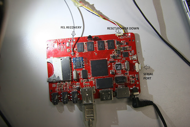
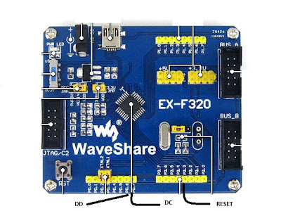
The next step was to locate the SmartRF04 debug pins on the EX-F320, these turn out to be the following pins:
![]()
![]()
![]()
An alternative to the CC debugger is to use the more expensive SmartRF04EB development board. The SmartRF04 essentially contains a C8051F320 and along with additional circuitry for level shifting and on board peripherals. The chipcon debug/programming interface for these TI chips is just 3 wires Debug Data, Debug Clock and RESET. Therefore the interface required from the board is minimal if we disregard the level shifting feature and assume 3 volts.
So I started searching for a C8051F320 board that could possible could do the trick, in the end I found the understated EX-F320 development board by WaveShare. Initially I wasn't sure whether it would possible to use this board or not but ordered one considering its low cost (approx £12+£4p&p). Luckily I already had a Silabs programmer to flash the EX-F320, in fact the Silabs programmer also uses a C8051F320! Its possible to build a cheap Silabs parallel port programmer or buy a cheap clone from Aliexpress.
Just over a week later I received the EX-F320, it came with 2 different USB cables for powering the board, 2 sets of 2 pin jump leads and 2 sets of 4 pin jump leads (I can't see the point of the 4 pin leads, it would have been better to supply individual jump leads!).
A powering up the EX-F320 and verifying it was recognised by the Silabls programmer I downloaded and installed SmartRF Studio (SRFS). Next I flashed the bootloader (srf04eb_bootloader.hex) and the firmware (fw0400.hex) to the EX-F320. These files are located in \Program Files\Texas Instruments\SmartRF Tools\Firmware\SmartRF04EB. A quick restart of the EX-F320 would determined if the SmartRF04 firmware would run or not. Fortunately after power up the EX-F320 was recognised by SRFS as a SmartRF04 board.

The next step was to locate the SmartRF04 debug pins on the EX-F320, these turn out to be the following pins:
P0.6 - DD (DEBUG_DATA)
P0.7 - DC (DEBUG_CLK)
P2.3 (RESET)
Ideally the 3 pins should be protected with a buffer circuit (74HC245/74HC244) possible with the inclusion of pin P2.2 to enable ouput (have to verify with the SmartRF04 schematic). The EX-F320 also produces a regulated +3.3v supply which can be used to power the board to flash/debug.
Final stage was to test (I tested without a buffer circuit) chip detection. I used Ciseco XRF CC1110 module in combination with their Xino basic board.


The CC1110 was also detected by IAR (kickstart) and could be programmed/debugged without any problems.
Another plus point is that the EX-F320 can be used for 8051 development once it is no longer required for CC development.